|
|
DigiBarn Stories:
The following is an edited transcript of the communications between the various members of the LINC restoration team members. The cast includes:
Threaded communications in reverse chronological order Initial Communications with the St. Louis and distributed LINC teams from Bruce Damer, Digibarn Curator (14 September 2006)
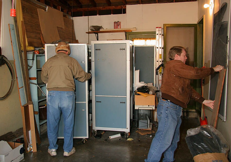
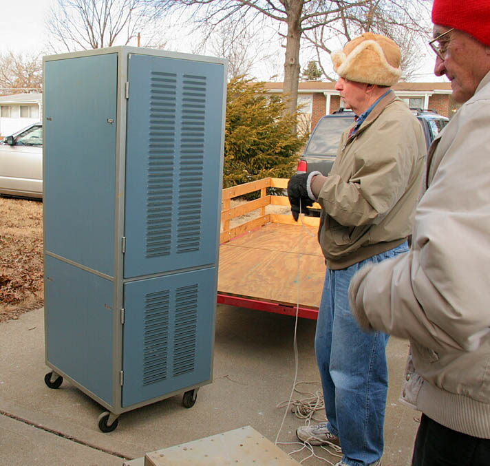
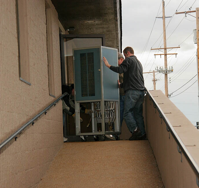
Hello Severo, Gerald, Scott and everyone, Bruce Damer of the DigiBarn here. Thanks for initiating all this. My goal in being a part of this would be to help bring to general consciousness the fact that the LINC is perhaps the first true "personal" (or at least portable) computer and get it more widely publicized. Every year we do an anniversary event here in the SF Bay Area and the LINC would be an admirable subject for next year (this year it is "Apple in the Garage" with Steve Wozniak et al). If this was all successful I would work hard here and find a way to arrange shipping from St. Louis (something always comes up, we managed to move two Cray supercomputers and a whole network of Xerox machines in years past). So if any restoration effort goes ahead you have my full (if remote) support and if any video or photos or text (Blog, reports) of the restoration were produced I would feature them on the DigiBarn site. I wish I had the technical skills to help but I can at least help to bring this to the attention of the computing history world. All the best and thanks again for considering taking this on! LINC-on! Bruce Initial technical concerns and some fun stories from Tom Chaney (14 September 2006) The Caps may be bad, but they can be replaced. Perhaps with a new capacitor about ½ the size of the original, but they can be replaced. Note I’m not playing strict Historian here, but these parts are inside and will not be seen. With the documents Scott Has, there should be no problem figuring out what each capacitor has to do, and testing or replacing the Caps as needed. Finding some working link tapes may be a bigger issue. I guess we could toggle in a program That just moved to a tape block with a non-working tape mounted. Not very satisfying. Bruce, when Scott was in early grade school, I would take him with me to work on Sat. He had his own Link Tape, and would pull a stool up to a Link, start up a machine and play games. The Link Made a great “baby sitter”. Toward the end of the Link era, my Scott had a working Link In his bedroom. By then, these “Apple” things were appearing and they had more appeal than a Classic Link, so he never did much with his first personal computer. One last story. Just after we set up the machine in his bedroom, Scott got in trouble at school and had to write sentences. He wrote a program and had the Computer print out the sentences. It ran a bunch of pages. I think the printer ( a modified selectric Typewriter) printed for a half hour. I remember it printed for a L-O-N-G time. I was so sure the teacher would be upset and throw the whole thing out that I let Scott do it. The teacher was so surprised to get the printed pages that he let the kid get away with it! And again later from Tom Chaney... I really used Link? Wow! It took me years to use the word “link”. I used “linc” in everything I wrote for a very long time. I was always fixing the spelling while proofing. Scott has 4 machines, which he claims all worked when he took them. One of the machines is the BCL tape formatting machine. So if we can at least get blank tapes That still have the iron oxide stuck to the tape, maybe we can re-build some stuff. . . . or better Yet, maybe we will find some good tapes. O-yes, in addition to the four machines, Scott has a fairly large collection of DEC modules, including extra memories. So If the “second” machine is just for parts, we may Be able to fill that need in a different way. O-yes, one of the machines Scott R. has IS the one Scott C. had in his bedroom. I forgot to tell Scott last night that this building is ramp equipped. His getting in and out here should not be a problem. Transistors typically don’t age. With four sets of stuff to work with, getting at least three working Power systems should not be hard. But if we DO need to buy replacement transistors, then yes, There is a problem here, or at least an interesting engineering job slowing down today’s parts to Work in yesterday’s systems. Tom From Gordon Bell (15 October 2006) I think we'd all like to see the LINC in operation. Having two of them would be great. The LINC really is the first PC as we know it. From Dick Clayton (16 October 2006) I surely support the idea of an operational LINC. It was the first practical integrated Lab System and a real "personal computer". All the components except possibly the power supply and tape drive are full of standard parts. Having one or two backup's would assure a good spares. The only other problems I could imagine are with the connectors, they are gold plated and have a limited number of insertions to their life. This probably wouldn't be a problem in a low vibration situation without high humidity. I would be happy to help or even lead such a venture if it became a project. I even saw the production tech for the LINC system @ DEC, (Jim Scanlon) last fall in Boston! Regards, Dick Clayton From Tom Chaney to "The Management" (25 January 2007) Dear Management, There has been some progress. Three of us gathered at Scott's house earlier this week to have a look at things. As are result of this "look", a meeting of the people (if not the minds) is set for this Sat. at 1:30pm (CST) to move two LINCs from Scott's home to the STS office space. Gerald, (yes even, Gerald) upon seeing the state Scott has kept the LINCs all these years was heard to say that these LINCs just m-i-g-h-t turn on and run. We will see. Scott needs to be recognized in some special way when this is all done and in place. The "people" meeting this Sat. include Scott (of course), Gerald, with his pickup, me with my Scott's Jeep, and maybe his trailer, and Jerry with his grandson in law (Troy) and his pickup and trailer and two wheel dolly. The move should happen in one trip. I trust that this report of the actions of the St. Louis contingent will at least change the color and texture of our "Mark" from a bright black to at least a dull gray. Tom Men at Work! Moving the LINCs (and parts etc)
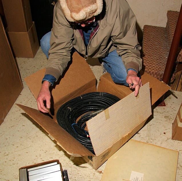
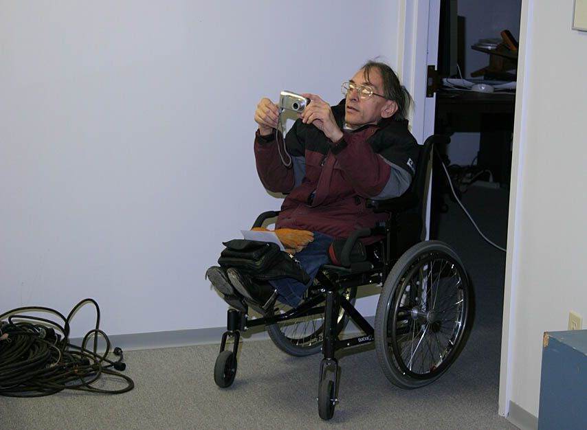
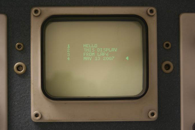
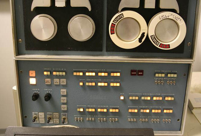
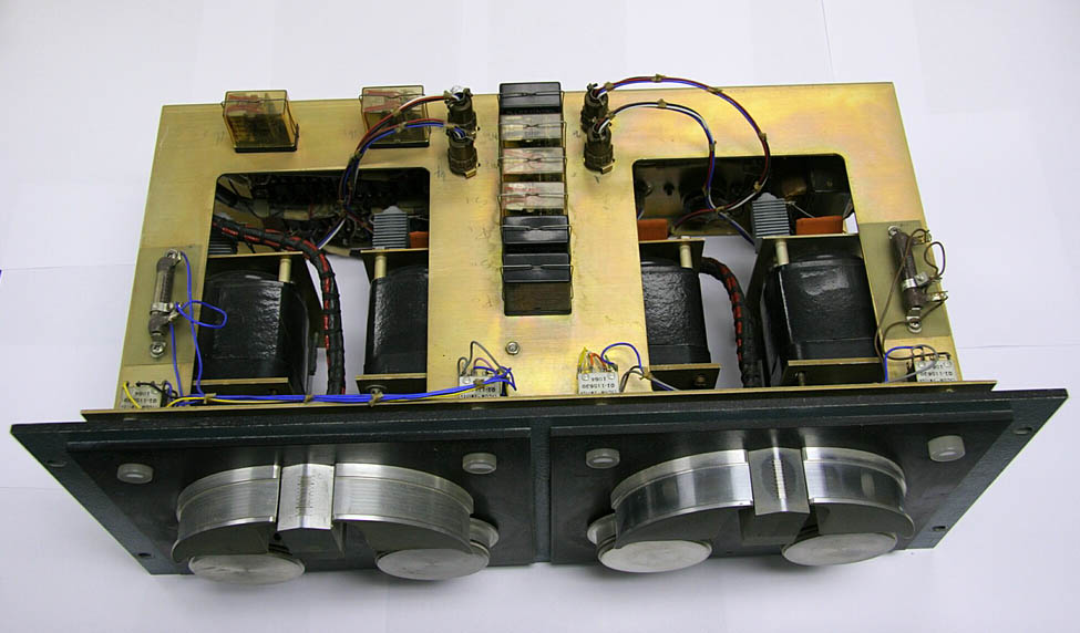
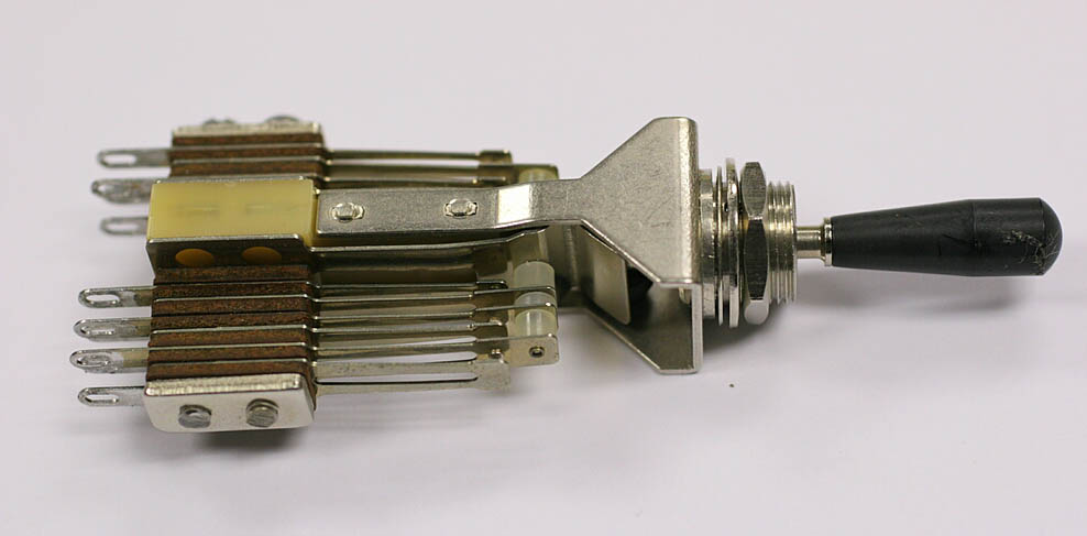
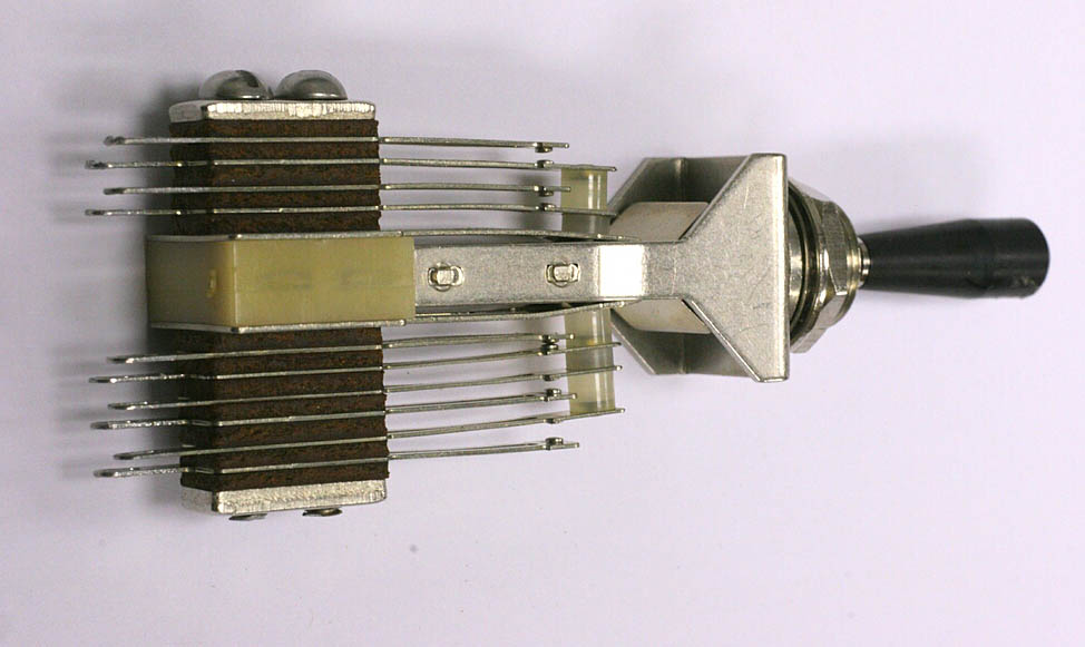
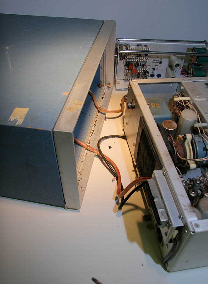
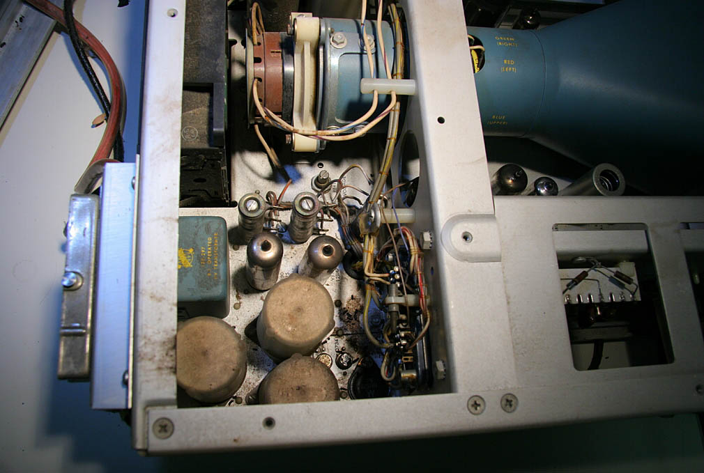
From Gerald Johns on the successful move of the LINCs (27 January 2007) Severo: gerald From Wes Clark later that day WAY TO GO! AND KEEP THEM PICTURES A'COMMING!! -- Wes From Severo Ornstein also later that day Eureka! Way to go, guys!! Thanks to everyone who helped with the move. I look forward to any pictures and to news of further developments. Wish I were there to help (and smell the burning resistors) - WHO said that? Onward and upward!! Restoration Report from Tom Chaney (19 February 2007) Hello, Gerald worked at least a solid day on the LINC last week and made some progress. The console is mostly working now, and the next thing was to store a few word program in the memory so we could test the display. The memory doesn't work. Gerald thinks it's the -3V supply. I have spent some time looking at the -3V, but haven't figured it out yet. Among other things, the -3V supply counts on it's load to work. At no load, the "-3V" supply puts out zero volts. So I tried to measure the -3V with the LINC running and everything hooked up. The documentation doesn't seem to agree with the memory driver board, so I'm not sure which connector pin should have -3V. Hard to debug when you don't even know which pin to look at! I've been doing a different puzzle (a PC board layout). I'm getting a little tired of my board layout puzzle, so I'll take a break this afternoon and puzzle over the LINC a bit more. Wes, I have the LED stage light driver/dimmer circuit mostly working. I ordered a different pot. Fri that will adjust the maximum current delivered to the lamps. This pot will function as a "color adjust" control. I have another pot that adjusts the lamp on time per cycle, and thus the lamp intensity All this works fine now. The really-really dim to lamps full off transition as you turn the pot is now nice and smooth. There is also a toggle switch that turns the lights on and off. So any intensity can be set, then the lights turned off. When the lights are turned back on, they will go to the set intensity When the lamps are switched on, the light level rises to the pre-set light level smoothly over a 1 to 3 second interval. Looks just like real stage lights coming up after in intermission. Back to the LINC, anyone have any handles for DO-TOG, etc. switches? They are black, about 1/4 inch in diameter, about 3/4 inch long, tapered at one end, and have a threaded hole in tapered end so the handle can screw onto a #6-40 threaded stud that sticks out of the switch. We have two switch handles, we need three per machine. I plan to buy a #6-40 tap and make a handle, but thought I would ask in case there was one about. The story goes that the handles were removed for the LINCs so the switches didn't get broken off in storage, and that all the handles were put in a common bag. That bag has not been found. Scott found two spare switches, complete with handles. That's were the two we have came from. NOTE: "normal" #6 machine screws have 32 threads per inch. The 40 threads per inch is not very common. One hardware store told me the sewing machine industry used the 6-40 screw system. Clearly not a big rush to get the switch handles fixed up. The switches work by pushing on the little threaded stud sticking out of the switch. It takes some pressure though, and one's finger gets a bit sore if the switches are used a lot. And just four days later on 23 February, 2007 from Tom Chaney... From the title you can guess at what comes next. As you will recall for the last message, the LINC memory was not working. Investigation had shown that the -3V supply was not working. Gerald remembered, or had worked out, that the -3V supply was mostly used by the core memory circuits. The -3V supply line measured about -0.24V. I started testing the -3V supply. The design of the -3V supply is such that it only works if there is a load on the supply. (the load goes between the -3 and -18V supplies, NOT from -3V to ground.) I placed a dummy load on the supply output, and the -3V supply worked fine! (note: I skipped over a few hours of finding where the -3V and -18V connections were in this discussion, but let us continue.) So yesterday morning, armed with the information of what the load needed to be to make the -3V supply work, we turned to the schematics, located a bunch of resistors that could be switched so that they are connected from -3V to -18V if the logic worked out just so, got out a spare memory and measured the resistors (the schematics skipped over labeling this set of resistors with their value!), did a bit of math, and by George, if all (or most) of these resistors were connected between -3V and -18V, then the total current draw would be about right to cause the -3v supply to operate correctly! So next we turned to finding the one logic signal that could cause the resistor switches to be off. In the process, we found that the resistor drivers were fed from the memory address bus in a way that only worked if all but one of the resistors were connected. The one resistor not switched on was then the Core drive line bit being addressed. So, this told us that the whole memory address bus had to be hosed to turn off all the resistor drivers at once. There were no control signals needed to be pulsed, all that was needed was the address bus ON, didn't even have to be working, just ON. AND THEN A Light Begin To Turn On. . . . . . You know, it's not like we had never pushed on the memory unit to make sure it was seated. We had. Several times. We had wiggled and pushed, and the memory unit just sat there. But yesterday, we pushed and shoved some more. We even removed the fan that spans both memory boxes so we could wiggle and push on just one box at a time. We were doing all this while testing the memory at the console. After we removed the fan, we got one bank of the memory to work for a little while! So now we pushed and shoved with earnest, but only got intermittent operation. So I went home and collected a 5 ft long two by four, and some smaller wood blocks, AND an 8 lb. sledge hammer. We had used it all, including the sledge hammer, by the time we got reliable memory operation. Those memory boxes ARE fully installed now! (O-yes, and the -3V supply is now measuring -3V.) Anyway, with the memory working, Gerald drew a line on the 'scope, and was able to move the line up and down with a knob. The delay works. With it set way down, you could see the line being drawn with a series of dots. The display box and it's knobs seem to be, at least mostly, working. We didn't test every knob or do anything complex on the 'scope screen. But it was good to all that do something that seemed about right. So, THAT was most of yesterday. We did move on a little to the next problem. There appears that only part of the Reset circuit is working. I replaced the DO-TOG / STOP switch. There is a note about bending the STOP switch contacts so that one set of contacts close before the other. I need to check that I have that correct. Gerald is planning on being here next Tue., and we have this (probably way over optimistic) hope of having some tape drive action by the end of that day. And on the 24th Tom Chaney writes on working up to the eight pound hammer!. There’s a lot of Charlie in me. He always insisted on working and re-working material before it was published. He drove the rest of us nuts! There is even a LINC document that was never released. We have located a boot leg copy of that document here in town. This document covers the LINC tape drive theory of operation. So where am I going here? I see some value in these stories. This is what really happens and how a “single point of failure” turned out to be that some 220 contacts were not made. Not the first place to look. I was thinking early this morning of how to expand this little story and your note got me going again. I took some pictures of a memory unit out of the LINC, and also a single card. A single CARD in the LINC has 22 pins, and is hard to get in and out. I don’t think one of the cards can just be pushed in. One has to wiggle up and down while pushing HARD to get the single card in. The memory unit has 10 rows of the same type connector, so a memory unit is 10 times as hard to plug in as a single card! I just removed a single card from the “spare” LINC and tried to plug it back in. I then tried to push an equal amount on a bathroom scale held on a wall at about the same height as the card I was pushing on to get some idea as to how hard I was pushing on the card. The bathroom scale read a little over 30 pounds, and I STILL had to wiggle the single card. So the memory unit takes over 300 lbs of push to get it in, IF you can push that hard and also wiggle up and down! When that much force is applied, it’s really hard to wiggle also. So I think this means that any real memory insertion scheme has to push quite a bit harder than 300 lbs. This is how we slowly work our way up to the 8 lb hammer! In fact, the 8 lb hammer banging on a block of wood held against the back of the memory box didn’t do it. I had to set the two by four board in place, acting as about a 3:1 mechanical advantage lever, and then bang on the end of the two by four, WHILE holding static force on the lever as I was banging. ( I was rocked back, with my weight hanging on the two by four near the end, but with my fingers back enough I could swing the hammer and hit the end of the two by four - - got the picture?) AND then I had to set the butt end of the two by four near the bottom of the back surface of the memory box, then toward the top end of the back surface, back and forth, to get the whole memory box to wiggle up and down as I was trying to drive the memory box forward. Severo’s right, we do need to get this on video. Tom And also on the 24th Severo Ornstein's note about Tom Chaney's historial role as "Mr. Glitch", interesting background on this member of the restoration team (24 February 2007)! Back when we started working on Macromodules (self timing logic) we first realized that all the synchronizers the world had been using were vulnerable because many assumed that flip flops would settle when hit by ambiguous signals within their usual turnover time. Tom is the person who demonstrated that that's not always true - that in fact in theory they could hang up for arbitrary lengths of time. To do this he had to create the ambiguous signals resulting from timing conflicts (e.g. one side of a gate opening up just as the other side shuts down) with very tight tolerances. He built special equipment to allow him to study these cases (vary timing very tightly) and was able to photograph the results demonstrating the problem. A whole generation of digital engineers had grown up believing that everything, including timing, was completely digital and, believe it or not, serious engineers (even at the holy MIT) debated whether glitches actually could occur. Tom became Mr. Glitch for a while. As you can tell, he's a fine engineer with Charlie's sense of carefulness and attention to detail - despite the sledge! Back to it with Gerald Johns (27 February 2007) There was not much progress today, but some in the negative direction. I have not lost my inverse Midas touch! This morning, the tape transport 1 seemed to be almost ready to work. I could exercise the RDE, CHK, and MTB instructions, and the tape sometimes would emit the characteristic chirp and compute a valid checksum. Reasonable-looking data appeared in memory after the read operation. Since transport 1 seemed better than transport 0, Tom soldered up a unit-interchange plug and onward we went. As the day progressed, the reliability of the tape went from marginal to incompetant. At the end, I could not even keep the tape moving with the motion bit on in the tape instructions. I brought home a reduced-size copy of Vol 12 in order to study the logic diagrams. On Thursday, I may do some swapping of the reader-writer cards, and I plan to try to follow the tape data to see if the mark, timing, and data channels are doing reasonable things. Of course, I have to have enough cooperation from the tape that it will keep moving when asked. gerald And at Long Last on May 16th, 2007 Tom Chaney writes (photos taken 14 May 2007 despite the date on the screen):
OK, so there are two pictures. * Not all that works, works all the time (A warm machine seems to be a happier machine.) *
Not all works at all yet * BUT I D-o-o-o-o CALL THIS PROGRESS!!!! Tom From Wes Clark (18 May 2007): Tom: GREAT NEWS! ! Clear proof that the PhoenixLINC is indeed coming back to life! I assume that Gerald is thrilled a bit too. -- Wes From Tom Chaney (21 May 2007): Bruce, I don’t think it’s quite time to schedule a truck. The tape system is still very fickle. Getting to a more solid state may be quick, and it may not. The notion of getting the LINC to California enough in advance of the “event” so there is time to fix what ever stops working during the travel is a very good idea though. Several, maybe “most”, of the fixes turned out to be just a mechanical adjustments. Replace bearings and belts in the tape drive, twist some potentiometers to adjust the power supply voltages in the display ‘scope power supply circuits., fully plug in the memory, etc. There is the one capacitor that had to be replaced to get the chime working, and Gerald has done some board swapping with the second machine at STS. (I view the second machine as slowly getting deader and deader as we work to get the first machine fully functional.) So there has been some electrical changes. November is now 5 plus months away. The LINC moved to the STS space on Jan. 27, a little less than 4 months ago now. Things to do: (with no input from Gerald, so this list is, by definition, is incomplete.)
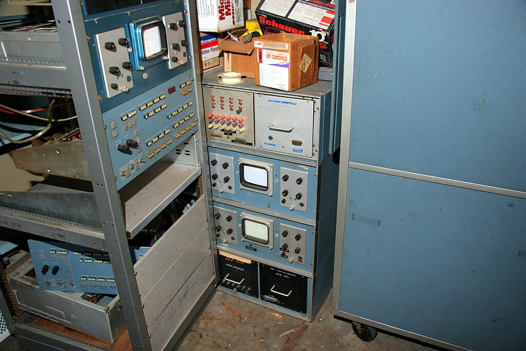
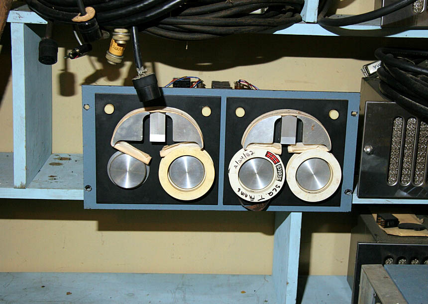
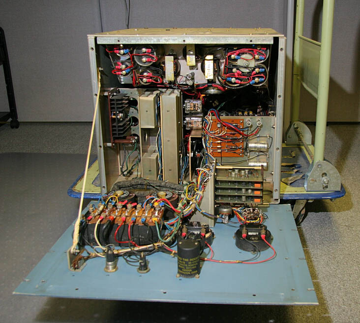
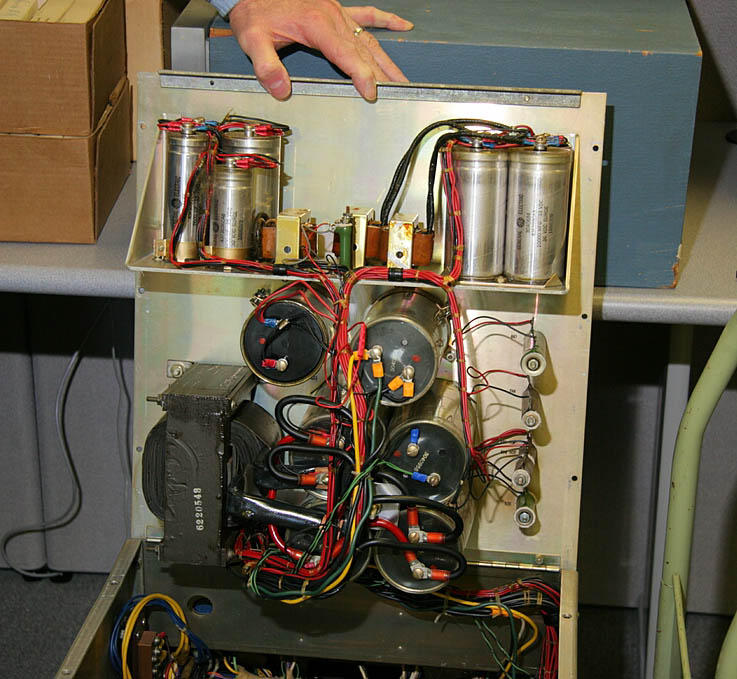
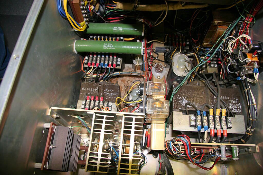
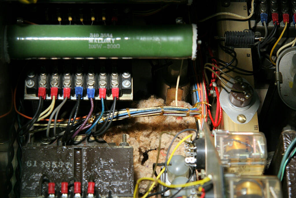
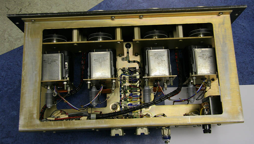
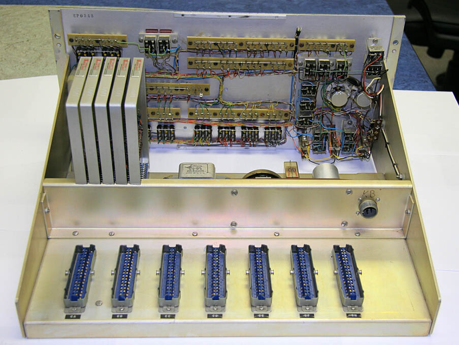
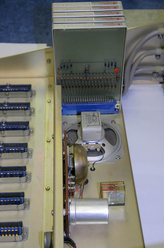
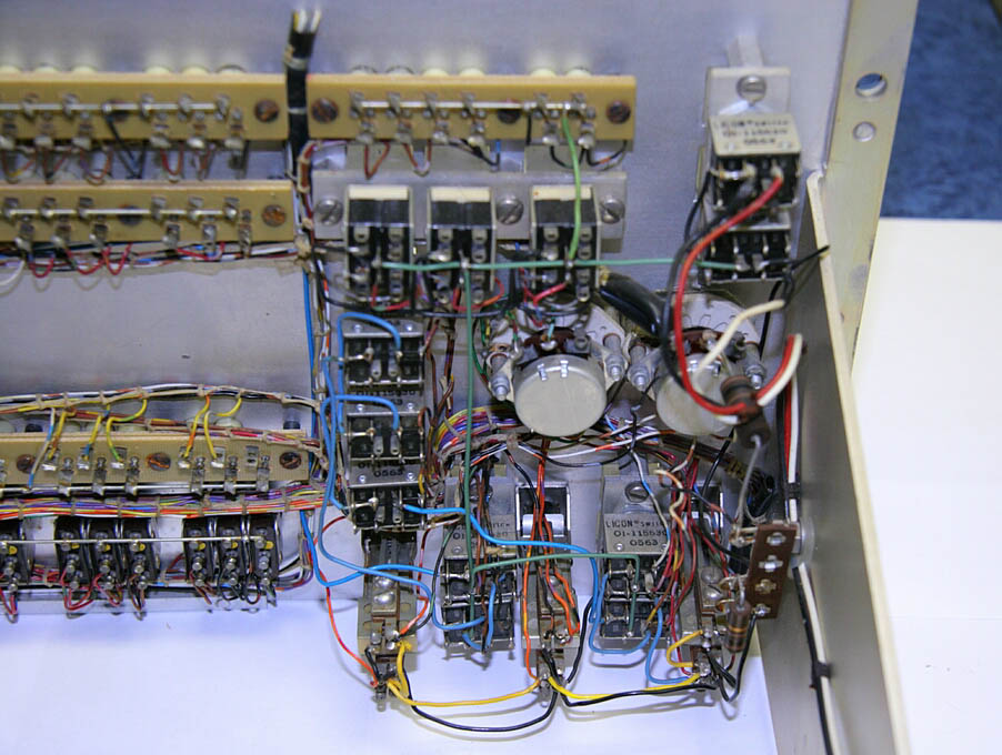
Maybe the best thing that has happened here at STS is that we are learning where to look first to fix problems. If the trip West does brake the machine, we may be able to “fix” it a second time there a lot faster. From Tom Chaney (22 May 2007) on Restoring a Second LINC (and keeping either of them working): I talked to Gerald about doing a second machine for St. Louis, and he is interested. We can fix anything in the display except the CRT itself. That's a special with long persistence phosphor. We can probably get a second display going, I just need to spend some time with the other displays. Depending on the discussion below and my descending list, we should probably send two working displays to Calf., so we need three of the four working to cover all spots. And Tom Chaney again, on negative LINC restoration progress, but just for a short time (29 May 2007): OK, things are back on track, maybe a little ahead. All in all, its been a reasonably good day! Skipping over the wild goose chases. (But which resulted in some really nicely polished main power line contactor contacts along the way!) The problem was the elapsed time meter! At 9633.8 hours, it choose to die, making some really horrible sounds. The meter is mounted in the middle of a 16 by 19 inch panel and was apparently resonating with the natural frequency of the panel thus making lots of noise. It's now disconnected. I got the elapsed time meter disconnected, turned the LINC back on, and tape unit 0 would not stop spinning! So maybe the power supply problems were bigger than I thought. After checking power supply voltages and wondering if I had REALLY fixed the power supply, I ended up re-seating the relays inside the tape drive console, and banging on them a bit. (soft bangs you understand) This fixed the unit 0 motors running. Upon playing with the button switches that make the tape drives run, it looked like the tape drive 0 motors were now acting more like tape drive 1, so I called Gerald, who gave me the switch settings, and loaded up LAP6 from tape drive 0 with no re-tries of the tape motion! It just read LAP6 in and ran! I've had the LAP6 running for almost an hour now with no problems. So it looks like we are close to having a working LINC. Although, we may continue to have set backs as things start failing. We'll just have to wait and see how things hang together. And Gerald has some more tests he wants to try. He's even beginning to think marking a tape! P.S. I just checked the LINC, still running. I even stopped and resumed the program a few times, it all works. Tom And Wes Clark responded: Fantastically good news!! Full marks for perseverance & fortitude!!! Gerald Johns writes a dash of cold water (14 June 2007): Severo: Tom and I both think that one LINC can be made to work just well enough to do a video (with some judicious editing), but there is no reasonable hope that one of the old machines would continue working as a museum exhibit. Jerry has expressed the desire to bring a second machine back to enough life to at least flash the lights in St. Louis. I think that with the four LINC machines that Scott preserved, we might be able to make the historical video, and get one to power up and look a little alive. We would not want to spread the parts over a wide geographic area, so don't send the truck just yet. Let us all talk, maybe after Tom and I can try to undo my last improvement to the tapes. Little changes, the inverse Midas touch is still in control. Gerald Pictorial selection of LINC hardware and internals Project Upate August 5, 2007 - and now we are planning on the finalization of the restoration there and planning for the move to the Bay Area of Northern California sometime in the Fall of 2007. Watch for the special event with the LINC(s) and members of the LINC and restoration crew at the 10th Annual Vintage Computer Festival (Nov 3-4th, 2007) at the Computer History Museum. |
||||||||
|
See Also:
Back to other Stories | ||||||||
Please
send site comments to
our Webmaster.
Please see our notices
about the content of this site and its usage.
(cc) 1998- Digibarn Computer Museum,
some rights reserved under this
Creative Commons license.